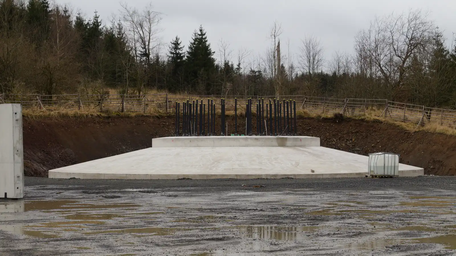
Wind Turbine Foundation
How the hidden concrete base carries the whole turbine, the main foundation types, and how grout and cracks are repaired.
Request a quoteGet a free quote
Matched to vetted providers in your state. No cost, no obligation.
How the hidden concrete base carries the whole turbine, the main foundation types, and how grout and cracks are repaired.
Request a quoteMatched to vetted providers in your state. No cost, no obligation.
The wind turbine foundation is the mostly buried concrete base that anchors the tower and carries every load the turbine produces into the ground. It is the one component an owner never sees once the site is commissioned, yet it decides whether the whole structure stays upright and still through decades of wind.
A wind turbine foundation does not mainly carry weight. The nacelle, rotor and tower are heavy, but the load that governs the design is the overturning moment: the wind pushing on the rotor and tower tries to tip the turbine over, and the foundation has to resist that leverage every second the machine runs. Because the wind gusts and the rotor turns, that load is cyclic, so the foundation and its connection to the tower are designed for fatigue as much as for strength.
Three foundation types cover almost all onshore turbines, and the choice is driven by the ground, not by preference. A gravity-base foundation is a large spread footing of reinforced concrete, often an octagon or circle, that resists overturning simply by its own mass and the weight of soil backfilled on top of it. It is the default where firm soil sits within a few metres of the surface, and it is by far the most common type on Australian wind farms.
A piled foundation is used where the surface ground is too soft or variable to carry a gravity base. A reinforced concrete pile cap sits on a group of driven or bored piles that transfer load down to competent soil or rock well below the surface. Piled foundations use less bulk concrete at the surface but add the piling rig, the piles themselves and the time to install them.
A rock-anchor foundation suits sites where sound bedrock is close to the surface. Instead of relying on mass, high-tensile steel tendons are drilled and grouted several metres into the rock and then post-tensioned, clamping a relatively slim concrete cap down onto the bedrock. It can be the most economical option on a rocky ridgeline, which is exactly where many good wind sites sit. A geotechnical investigation of the ground decides which of the three is specified for each turbine position.
A gravity-base foundation for a modern multi-megawatt turbine is a substantial structure. The footing is commonly 15 to 20 metres across, it is excavated 3 to 4 metres deep so it bears on sound ground, and a central pedestal rises about a metre above the surface to keep the steel connection clear of water. A single foundation often consumes 500 to 1,000 cubic metres of concrete and 50 to 120 tonnes of reinforcing steel, which is why a batching plant is frequently set up on or near a large wind farm.
Depth is where the foundation types diverge most. A gravity base stays shallow and wide. A piled foundation drives its piles much deeper, commonly 10 to 30 metres, chasing load-bearing strata below soft ground. A rock-anchor foundation is shallow at the cap but reaches down through grouted tendons into the rock. In every case the real size and depth come out of the geotechnical report and the turbine maker's loads, so two identical turbines on different ground can have very different foundations.
Building a foundation follows a tightly sequenced routine because once the concrete is poured there is no going back. The crew excavates to the design level and casts a thin blinding layer of lean concrete to give a clean, flat working surface. The reinforcing is then tied in place as a dense rebar cage, with radial and ring bars sized to carry the tension that the overturning load puts into one side of the footing.
At the centre sits the tower connection, and there are two common forms. An embedded can (also called an embedment ring) is a large steel cylinder cast into the concrete, and the tower bolts to a flange on top of it. The alternative is an anchor-bolt cage: a double ring of long, high-strength bolts held between an upper and lower template, cast into the concrete so the threaded tops project to receive the tower base flange. Either way the connection must be set dead level and exactly on position, because the whole tower is referenced from it.
With the cage, embedded can or anchor bolts and the formwork in place, the concrete pour is carried out, ideally in one continuous operation so there are no cold joints in the structural core. Large pours are planned around concrete supply, temperature and vibration to keep the mix dense and free of voids. The concrete is then cured, the formwork struck and the pit backfilled, leaving only the pedestal and the bolt ring exposed for the tower.
The joint between the steel tower and the concrete foundation is the single most important detail in the whole base, and grout is what makes it work. When the tower base flange is landed on the anchor-bolt ring or the embedded can, it is set on levelling nuts or shims and then a high-strength, non-shrink structural grout is placed to fill the gap between the underside of the flange and the top of the concrete pedestal.
That grout bed is not cosmetic. It spreads the clamping force of the tensioned anchor bolts evenly into the concrete and gives the connection a continuous, fully bedded contact so the tower and foundation behave as one. If the bed is thin, poorly mixed, placed with voids, or simply overloaded over time, it starts to crush and the connection begins to move. The whole turbine above sits on this one interface, so keeping it sound is a core part of structural maintenance for the tower and base together.
Grout and connection problems are among the more common structural issues on ageing fleets, and the warning signs are usually visible at the base. Crews look for grout crushing or spalling under the tower flange, a gap opening at the steel-to-concrete interface, rust staining running down from the connection, radial cracks spreading across the pedestal, and anchor bolts that have lost tension. Left alone, a little movement quickly becomes more movement as each gust works the loosened joint.
The repair is well established but specialised. A typical sequence is to investigate and map the damage, relieve and then re-tension the anchor bolts to the maker's specification, cut out and remove the degraded grout, re-grout the connection with a high-strength, low-shrinkage structural grout, and seal and recoat the exposed steel and concrete to keep water out. Cracks in the concrete itself are routed, cleaned and injected with a structural resin where appropriate. Because getting this wrong risks the whole turbine, owners route foundation grout repair, anchor-bolt tensioning and protective coatings to specialist independent crews rather than general contractors. If you are weighing up timing, our blog on the Australian fleet leaving warranty covers how base inspections fit into a post-warranty plan.
Foundation work sits with the structural end of the industry. Inspection, grout repair, anchor-bolt tensioning, crack injection and coatings are all handled under tower, foundation and nacelle services, the same crews who look after the tower connection above the base. Matching that work to a provider who has done it on your turbine platform matters, because the grout spec, bolt pattern and tensioning procedure vary between makers.
Tell us the turbine platform and what you are seeing at the base, from grout crushing to loose bolts. We match you to independent foundation and bolt-tensioning crews.
Your enquiry is sent to vetted service partners who may contact you directly. We never charge owners or asset managers.